Test probes are used for the testing of electrical and electronic components and assemblies, for example printed circuit boards, wire harnesses, and plug connectors. All spring-loaded test probes measure electrical currents and have a similar operating principle with spring-loaded plunger and recommended working stroke. All products from the test probes range are also available via the product finder.
INGUN offers customers an unsurpassed variety of spring-loaded test probes. The individual series differ mainly with regard to material, tip style and diameter, spring force and installation conditions. Our test probes are characterised by the high quality of the individual components combined with precision and durability in the application. As a partner for electronics production, we combine expert knowledge with the skill to implement this and a worldwide presence.


Finding the right tip style
and the right product
Many tip styles can be used for several applications. In addition, the test point can be characterised according to its size and surface condition - oxidized, clean or perhaps soiled by residues from the soldering process.
Depending on the DUT and test conditions, it may be necessary to test several tips styles and spring forces to find the optimum combination - and thus the right test probe.
Probe (GKS) design and function
Spring-loaded test probes (GKS) usually consist of three individual parts. The individual parts must be manufactured with the level of precision that is also required by microelectronics, e.g. for printed circuit boards. The plunger with various tips styles which contact the test point is the main element that is visible.
It must ensure low contact resistance between the probe and the device under test (DUT) in order to measure electrical currents without distortion. The materials used for plungers are steel and beryllium copper (CuBe), both hardened, and brass for very passive tip styles.
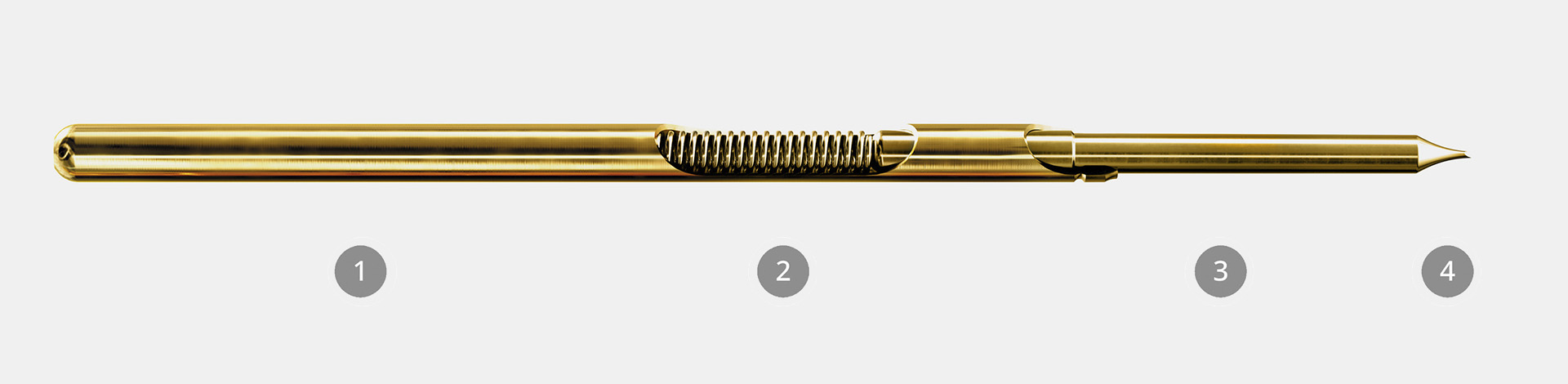
Image caption:
- Spring
- Barrel
- Plunger
- Tip
The spring is the active component and ensures the required contact force, even after one hundred thousand mechanical contacts (load cycles). The nominal spring force, which can be found in the catalogue and product finder, is achieved with the recommended working stroke and is subject to slight fluctuations depending on the design, manufacturing tolerances, and operating conditions.
The barrel accommodates the plunger and the spring. The electrical measurement signal or current flows through the barrel to the receptacle. To improve the plunger’s movement in the barrel, the barrel has a thin organic protective layer in addition to the gold plating.
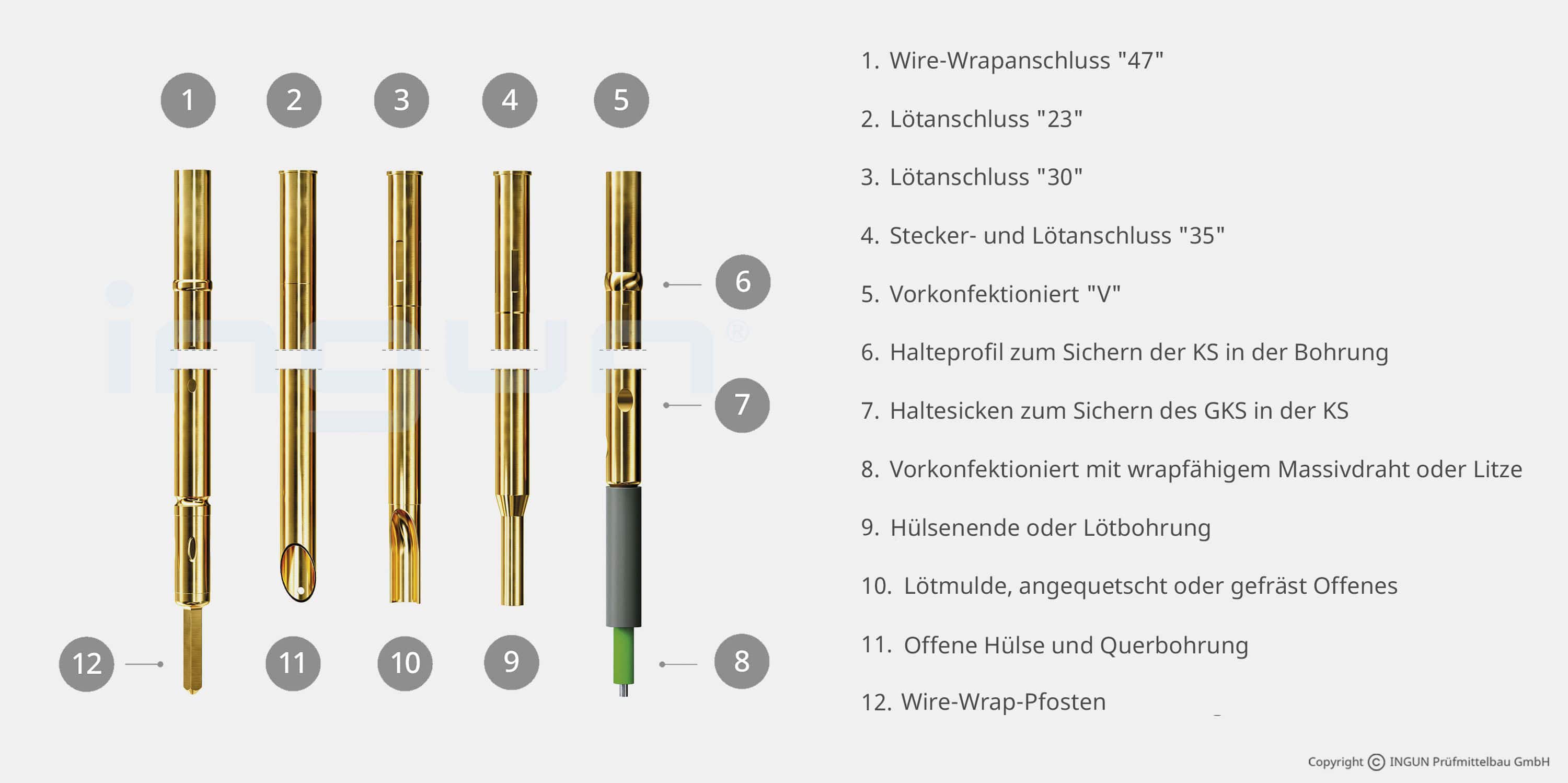
- Wire-wrap connection "47"
- Solder connection "23"
- Solder connection "30"
- Plug or solder connection "35"
- Pre-wired "V"
- Profiles to balance out assembly hole tolerances
- Crimping points to secure the test probe in the receptacle
- Pre-wired with wrapable solid or flexible wire
- Open-ended receptacle or soldering hole
- Solder connection pressed or milled
- Open end with hole for inserting wire
- Wire-wrap post