
5G/6G TEST TECHNOLOGY
5G and 6G applications pose new challenges for internal connectivity and its testing. With the HFS-511 and HFS-556 series, INGUN has RF probes in its portfolio that can perform automated, reliable tests on mixed-signal board-to-board (B2B) connectors in mass production.
What comes after 5G?
While the new telecommunications standard 5G has not yet been fully rolled out in all countries, scientists are already working on its successor: 6G. While the goal of 5G is to dramatically increase the bandwidth available to end users on mobile devices, e.g., to enable video streaming in 4k or even 8k resolution for several users simultaneously, the goal is also to connect trillions of devices to the network. These are, for example, sensors that transmit their measured data wirelessly, which usually requires only low data rates. This is also referred to as the Internet of Things, or IoT for short. The third and last area of application for 5G is to enable communication in real time, i.e., with the lowest possible latencies. This is also necessary to make applications where safety is a key factor, such as autonomous driving or remote operations, possible in the first place.
What the new mobile communications standard 6G will offer in future is undoubtedly exciting for both consumers and industry. In addition to expanding the applications already envisaged for 5G (greater bandwidth, even more connected devices, and even shorter latencies), above all 6G aims to further merge the real world with the virtual world and expand it to include applications such as truly immersive extended reality, or XR for short, and high-fidelity holograms.
In contrast to the 4G mobile radio standard, which brought with it the introduction of LTE and the associated frequencies up to a maximum of 6 GHz, the applications in 5G and 6G require wider frequency ranges up into the mmWave range. However, this also means that communication must be directional and point-to-point. This not only affects the RF front-end of the communicating devices, but also the connectivity within the devices, for example to connect an antenna phase array with a logic board.
Mixed-signal board-to-board (B2B) connectors
So-called mixed-signal board-to-board (B2B) connectors are used in modern consumer devices such as smartphones. These allow the transmission of a wide variety of signals such as radio frequency (RF), high-speed digital (HSD), low-voltage digital signal (LVDS), but also the power supply for consumers combined in just one connector. The connectors are designed to enable them to either, as the name suggests, directly connect two rigid printed circuit boards (PCBs) or a rigid and flexible PCB. The "all signals in one connector" approach is particularly advantageous in devices with limited space, as only one connection between two modules is required, which can also be designed as a flexible PCB.
The B2B connectors used differ in terms of their design, the number of electrical contacts they have, and the distance between these electrical contacts (pitch). B2B connectors in use today have a pitch of 0.35 mm, but connectors with a pitch of 0.30 mm are also available. B2B connectors of the first generation have a double-row design. The PCB designer can basically freely decide how to assign the electrical contacts. However, the small distance between the contacts, even when using several ground connections, poses a great challenge to achieve a sufficiently high RF isolation between adjacent signals. To optimise RF isolation, the two rows of contacts of the B2B connector can be separated from each other by an additional shielding barrier, if provided. B2B connectors of the second generation also have front-end contacts that are additionally shielded and specially designed for signals of higher frequencies in the mmWave range. The remaining double-row contacts are used for either low-frequency or other signals.
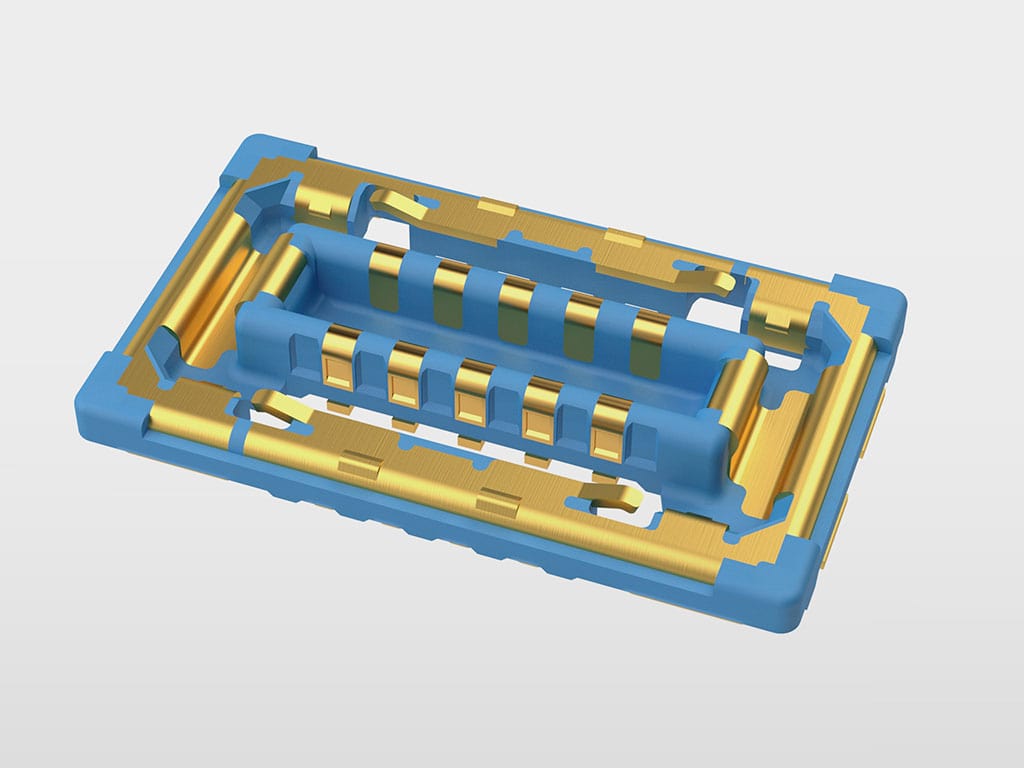
First-generation B2B connector:
The contacts are arranged in two rows.
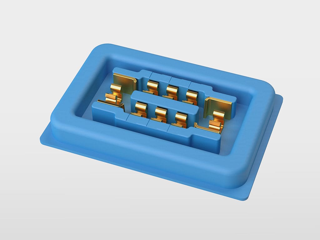
Second-generation B2B connector:
Front-end RF contacts ensure gut RF isolation.
Test technologies for B2B connectors
The presence of a wide variety of signals and multiple electrical contacts inside the connector housing also poses unique challenges for testing, because the test solution used must not only be able to transmit all signals without error but must also ensure that the B2B connector soldered onto a PCB can be contacted with repeatable accuracy to ensure reliable test results. There are different testing approaches.
- (Advanced) Interposer: This is a PCB with an original mating connector installed in a type of clamp mechanism. The operator often has to insert the DUT manually into the interposer. Another disadvantage of this method is that the original connector is not designed for long service life and is subject to wear, requiring replacement of the test solution after only a few thousand contact cycles.
- Test socket: The test sockets, which are usually equipped with blade pins or double spring-loaded fine-pitch (semi-conductor) probes (SCP), are applied to printed circuit boards to transmit the test signals via these to the test system. The test socket reproduces the mechanical contours of the connector to be contacted. However, the required tolerance compensation is only possible to a limited extent. Test sockets are mainly used for testing digital signals, e.g., from camera modules.
- Test probe: Test probes are spring-loaded probes which, due to their specific design, are particularly suitable for compensating tolerances on electronic circuit boards. These are usually positioned below or above the DUT and brought towards to the DUT during the contacting process. The use of springs also ensures that at the working point, the so-called working stroke, there is a sufficiently large contacting force to enable stable, repeatable measurements. The movement of the test probe is perpendicular to the DUT. By selecting suitable tip styles, contacting can be passive or active (for example, penetration of layers of contamination).
Advanced Interposer:
The DUT is usually guided by hand
Test socket:
Utilising blade-pin or fine-pitch technology
Test probe:
Compensates for tolerances using multi-level floatation
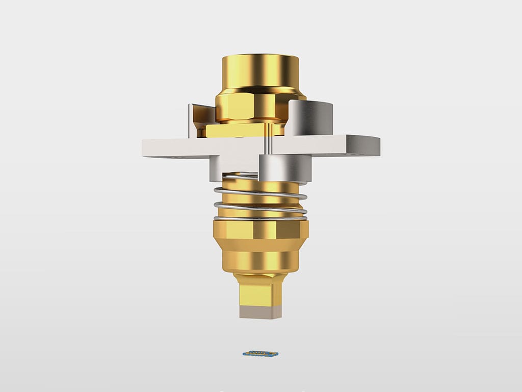
INGUN HFS-511 and HFS-556
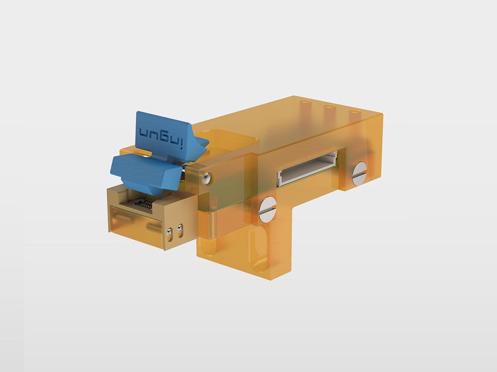
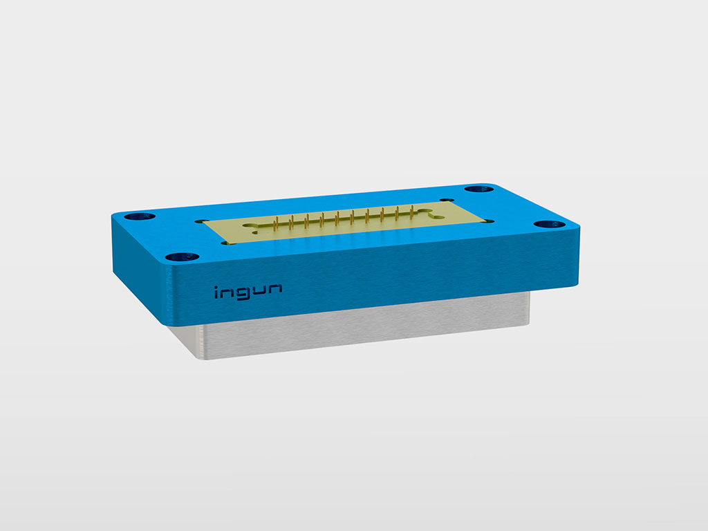
With their HFS-511 series for first-generation B2B connectors and HFS-556 series for second-generation B2B connectors, INGUN offers test solutions for mass production which combine the good radio frequency characteristics of interposers with the precision of test sockets to a robust test probe for automated testing. The test probes offer multi-level floating as well as full shielding and signal integrity. The test solution is very easy to integrate into test fixtures due to its two-hole flange. With an additional feature, the flange also ensures that the test solution is always mounted in the correct orientation. The connection to the test system is made via cable pigtails.
In contrast to other test solution approaches such as advanced interposers and test sockets, the HFS-511 and HFS-556 probes offer several advantages, especially in the harsh production environments common in mass production. Their mechanical design ensures long service lives; if necessary, the test solution can also be exchanged in just a few steps by loosening the two screws and the electrical connections to the test system. The multi-level floating of the test solution provides the required tolerance compensation that comes with connectors soldered onto PCBs. The test probe first aligns itself with the outer contour of the B2B connector. When approaching the connector, the probes compensate for any angular and rotational errors. At the working stroke, contact of the spring-loaded inner conductors and the outer housing on the B2B connector finally ensure a sufficiently large contact force that does not damage the sensitive contacts of the B2B connector yet ensures reliable and repeatably accurate contacting.
INGUN HFS-511:
RF test probe to test first-generation B2B connectors
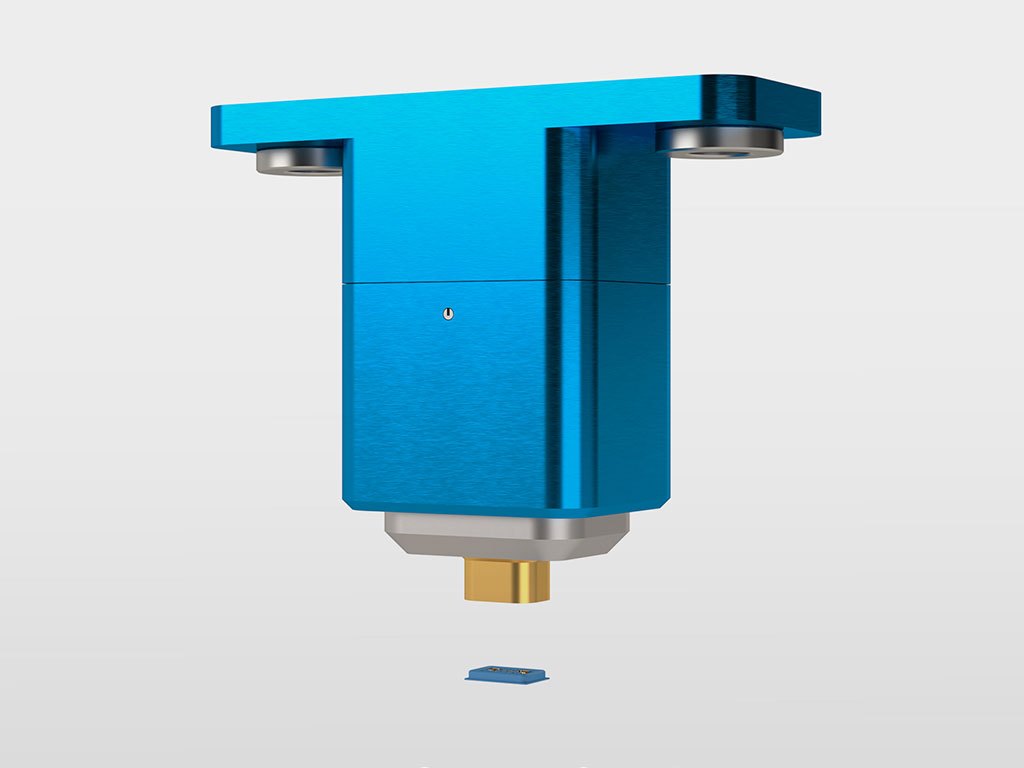
INGUN HFS-556:
RF test probe to test second-generation B2B connectors
Calibration
The design not only guarantees reliable, accurately repeatable contacting of the B2B connector with high RF performance and good RF isolation, it also enables calibration within the test fixture in the working stroke of the test solution. To do so, the DUT is substituted by a calibration substrate, each of which represents one of the components required for a SOLT calibration. The additional electrical length and phase shift introduced by the calibration substrate can be compensated by a simple fixture offset in the measuring test system.
Advantages at a glance:
- Only a small keep-out area around the test pad is required for the test probe
- Contacting of other test pads directly next to the B2B connector possible by piggyback attachment
- Multi-level tolerance compensation of axial and rotational errors
- Outstanding service life thanks to robust mechanical design
- Easy exchange thanks to two-hole flange installation
- Design mechanically prevents misalignment during installation
- Impedance-matched design and full shielding for excellent radio frequency characteristics and good RF isolation
- Simple standard SOLT RF calibration at the working stroke of the probe possible
- Flexible connection to the test system via cable pigtails
Summary
Various signals are combined in mixed-signal board-to-board for internal connectivity for the realisation of 5G and 6G applications. Different technologies are used to test these connectors. With the HFS-511 and HFS-556 series for first and second generation B2B connectors, INGUN offers high-performance test probes that can transmit the mostly radio-frequency signals to the test system with repeatable accuracy. The mechanical design allows an easy integration into test fixtures, as the required tolerance compensation during contacting is already integrated into the test probe.

- For testing HSD connectors (Rosenberger)
- Used for the transmission of high-speed data for navigation and entertainment in automotive engineering.
- For high data rates, e.g. LVDS signals, GVIF or USB
- Freely movable bearing
- Installation: press directly into the mounting plate or via flange mounting
- Cable interface optionally with original HSD plug as well as INGUN plug

- For testing FAKRA-mini connectors e.g. HFM (Rosenberger) or Mate-AX (TE Connectivity)
- Used mainly in future technologies for the automotive market (e.g. autonomous driving)
- Radio-frequency test probes for best radio frequency performance and data transmission
- Modular design, test probe combination for single, double or quadruple housing can be used or installed in floating mount HAS-807
- Cable interface high-speed SMPM male, connection cable SMPM female

- Long standard series
- Up to 2 GHz
- Cable interface MCX
- Plug-in version
- Receptacles: KS-810, KS-810 R, KS-810 F

- Long standard series
- Up to 6 GHz
- Cable interface MCX
- Plug-in version
- Receptacles: KS-810, KS-810 R, KS-810 F

- To adapt the interface of radio-frequency probes in the HFS-810, HFS-840, HFS-860, HFS-410 and HFS-440 series.

- For testing differential connectors (e.g. LV 214 / USCAR)
- Used mainly in future technologies for the automotive market (e.g. autonomous driving)
- Consistent radio-frequency performance for data transmission
- Modular design, test probe combination for single, double, or quadruple housing
- Cable interface H-MTD

- Long standard series
- Up to 4 GHz
- Cable interface MCX
- Plug-in version
- Receptacles: KS-810, KS-810 R, KS-810 F

- For contacting plug connectors, micro-connectors micro-switches
- Up to 12 GHz
- Cable interface SMA
- Installation via flange mounting