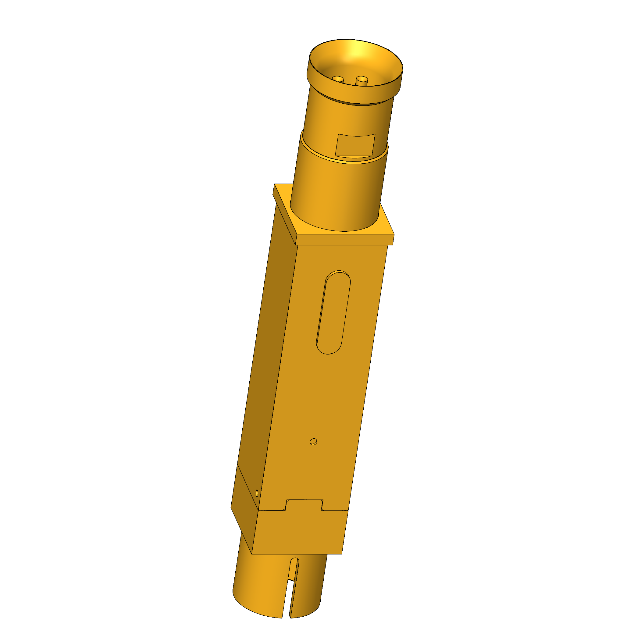
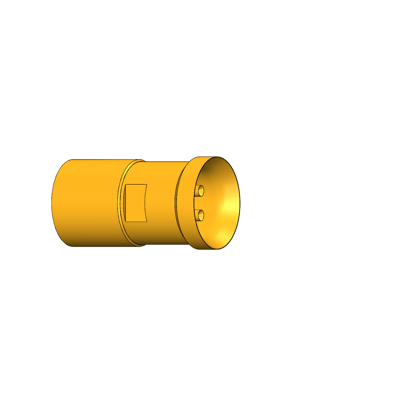
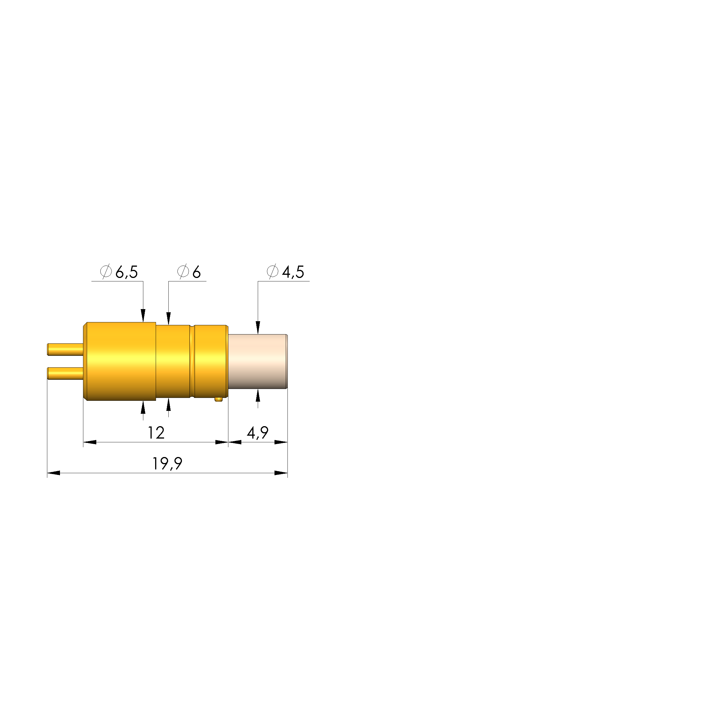
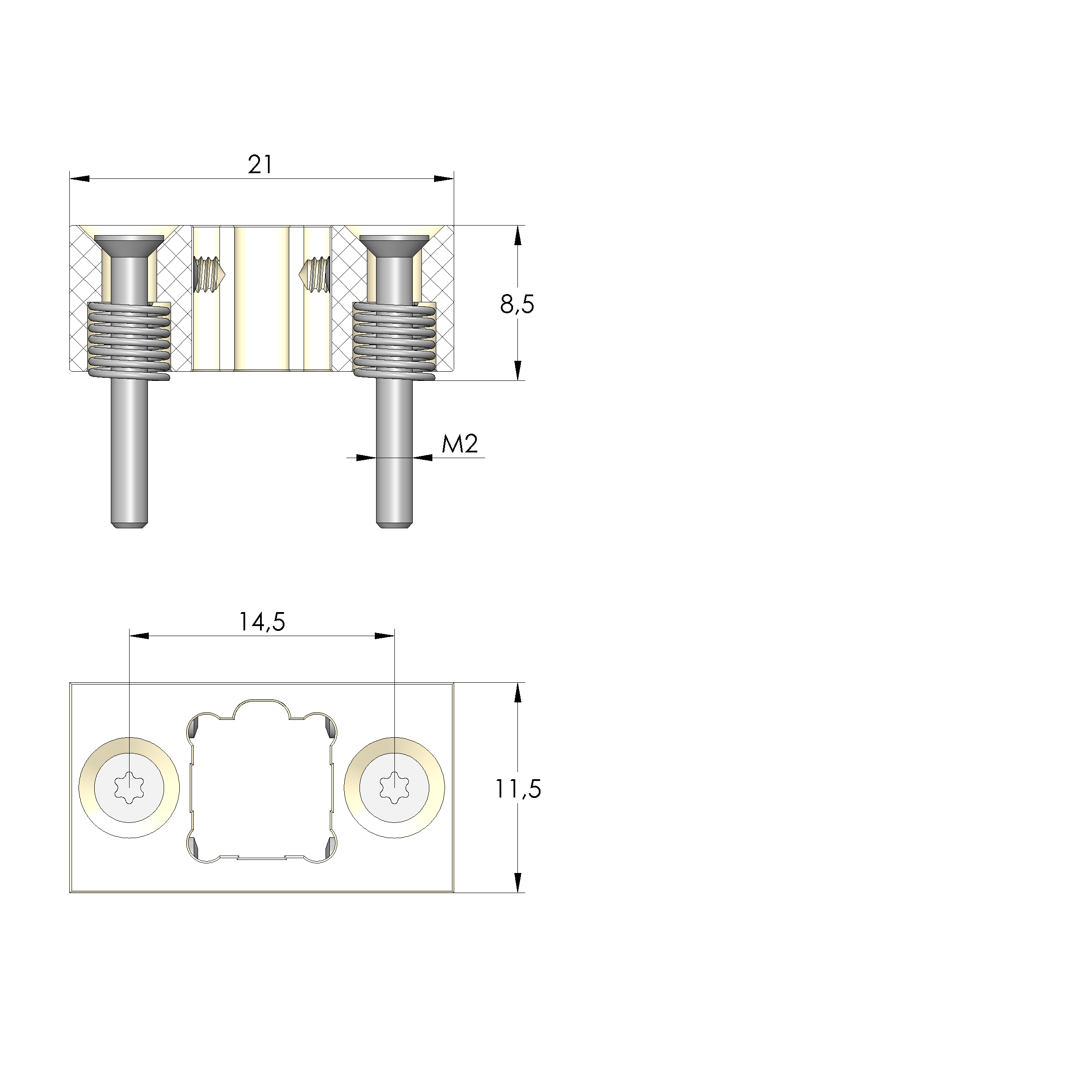
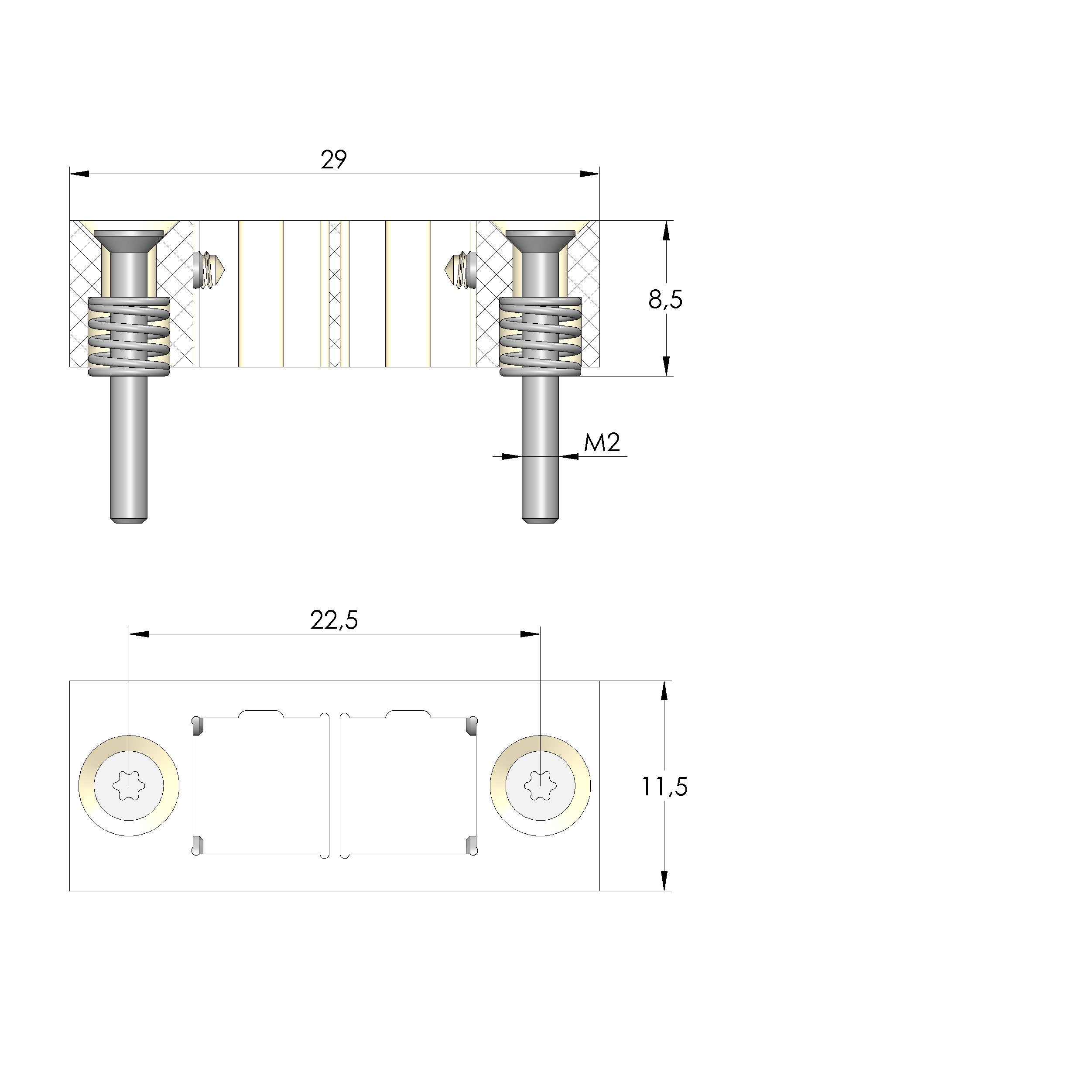
Radio-frequency probe HFS-819 303 090 A 20743 V2 Item HFS-819-0023
- For testing HSD connectors (Rosenberger)
- Used for the transmission of high-speed data for navigation and entertainment in automotive engineering.
- For high data rates, e.g. LVDS signals, GVIF or USB
- Adjustable storage of the HFS-819
- Installation: press directly into the mounting plate or via flange mounting
- Cable interface optionally with original HSD plug as well as INGUN plug
Radio-frequency probe HFS-819 303 090 A 20743 V2 Item HFS-819-0023
Please log in to show the price
Login
The prices listed in the scale are displayed rounded, therefore deviation in the total price is possible.
Shipping costs
* The prices are rounded to two decimal places.
Technical data
| Product group : | HFS radio-frequency test probes |
|---|---|
| Series : | HFS-819 |
| Sub-series : | HFS-819 plug, press-in |
| Grid : | 12 mm |
| DUT / contact : | HSD |
| Installation type : | Plug-in |
| DUT interface gender : | M signal conductor male / pin |
| Floating mount : | No |
| Non-rotating : | Yes |
| Continuous plunger : | Yes |
| Interface of compatible assembly : | SE-819 V2 plug, press-in, for HFS-819 |
| Compatible assembly interface gender : | F signal conductor female / socket |
| KS sub-series : | HAS-819 160, HAS-819D8 160 floating version |
| Min. temperature : | - 40 °C |
| Max. temperature : | + 80 °C |
| RoHS-compliant : | RoHS-3;6c |
| Outer conductor tip style : | 43 centring for outer side of connector |
|---|---|
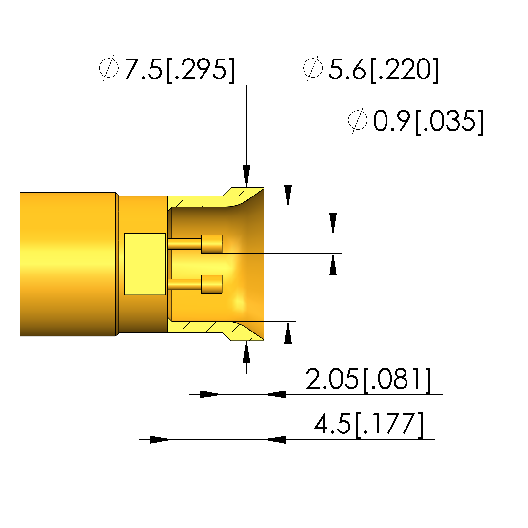
| Outer conductor tip style diameter : | 7.5 mm |
| Spring force of entire outer conductor at working stroke : | 15.5 N |
| Outer conductor working stroke : | 5 mm |
| Outer conductor maximum stroke : | 6 mm |
| Exchangeable outer conductor : | KO-819143750A-V2 |
| Outer conductor max. current load capacity : | 3 A |
| Inner conductor tip style : | 03 inverse cone |
|---|---|
| Inner conductor tip style diameter : | 0.9 mm |
| Inner conductor tip style material : | 3 CuBe |
| Inner conductor tip style surface : | A gold |
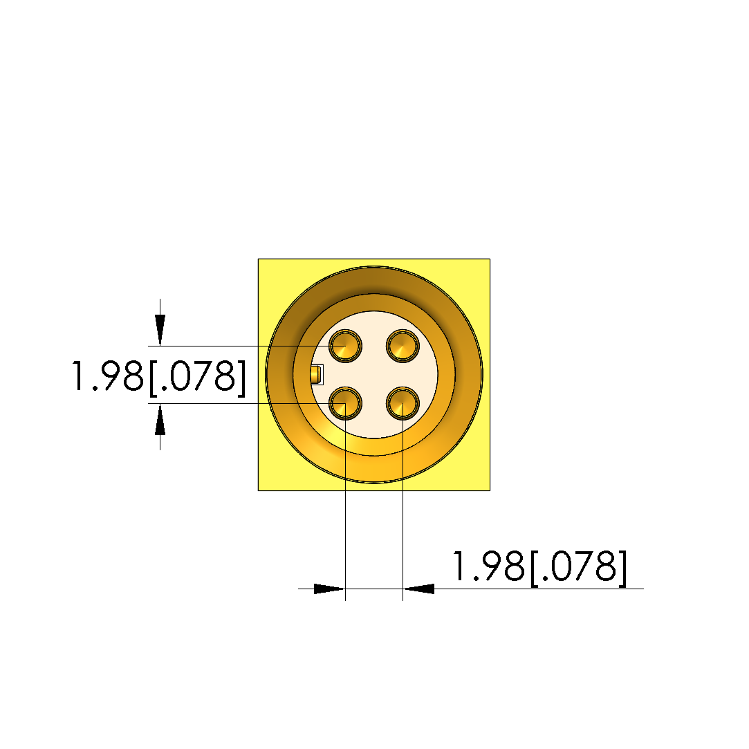
| Number of inner conductors : | 4 2 differential pair |
| Exchangeable inner conductor : | GKS-051-0017 |
| Inner conductor working stroke : | 2 mm |
| Spring force of each inner conductor at working stroke : | 1.3 N |
| Inner conductor maximum stroke : | 3.7 mm |
| Inner conductor max. current load capacity : | 3 A |
| Impedance : | 100 Ohm |
|---|---|
| Dielectric strength : | 1.2 kV |
| Total spring force at working stroke : | 20.7 N |
|---|---|
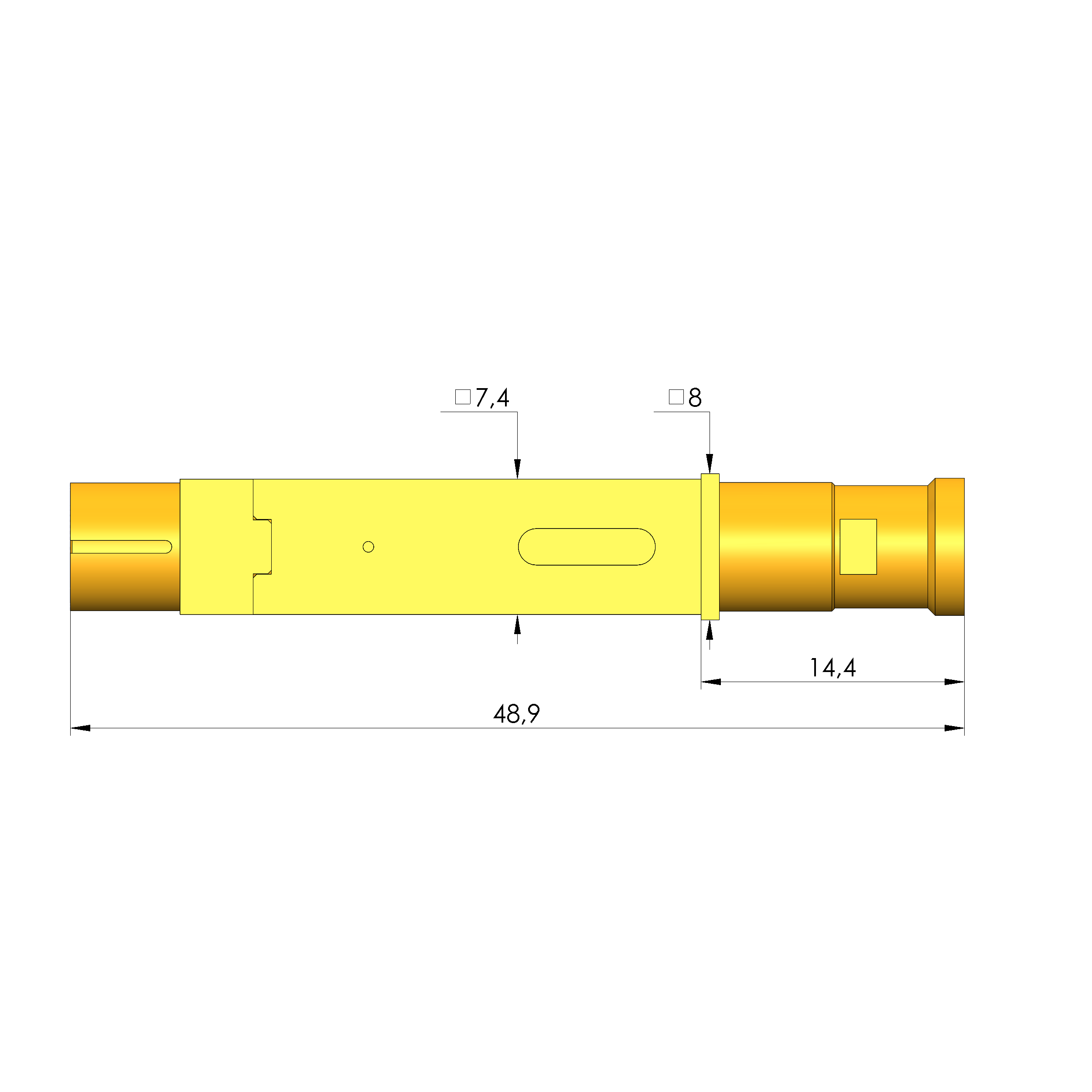
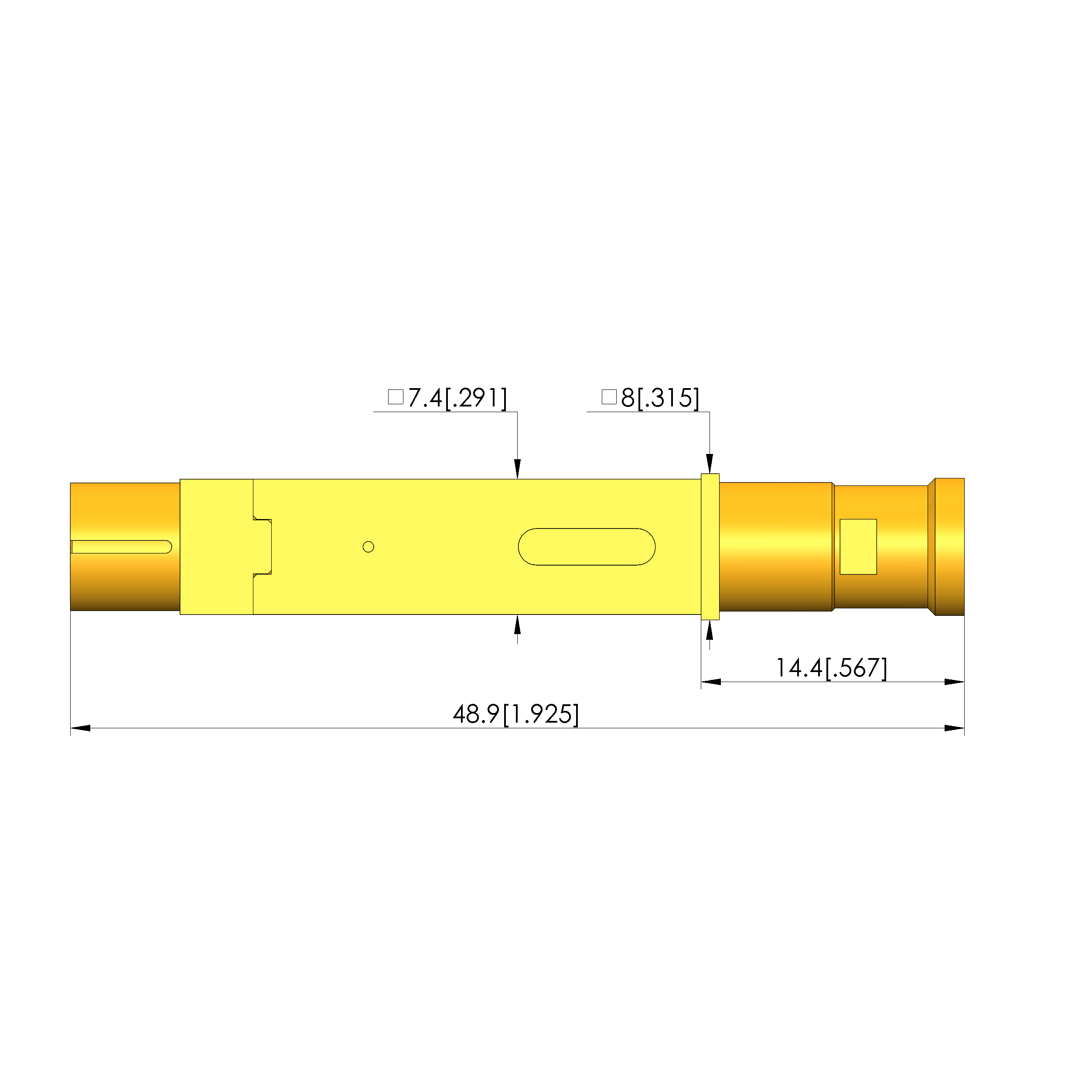
| Total length : | 48.9 mm |
| Barrel diameter : | 7.4 mm |
| Installation height without receptacle : | 14.4 mm |
